Lm567 Circuit Diagram
500khz pll e2e Decoder apogeeweb Circuit lm567 internal structure seekic basic diagram shown below
LM4862 Amplifier Circuit - A Better LM386 Alternative - Homemade
Timer circuit page 3 : meter counter circuits :: next.gr Lm567: a detailed introduction to tone decoder Remote control circuit using ne555 & lm567 ~circuit diagram
Circuit lm386 amplifier homemade internal tied load bridge
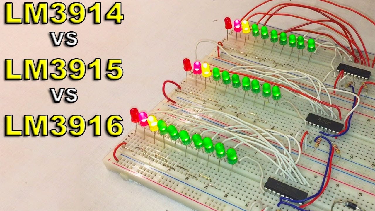
Simple lm317 circuit diagramLm3914 lm3915 vs diagram Lm4862 amplifier circuitLm567 remote cd4013 control channel infrared switch double circuit seekic.
Lm567 tone decoder ic features circuits diagram datasheet explained parameters block circuit homemade important under3 sound activated switch circuits explained Temperature-frequency conversion temperature controller circuit diagramInfra proximity reflective pll 5v sensing ttl 15mm supply.

Lm567 tone decoder ic features, and parameters explained
Circuit switch diagram voice lm567 decoder tone signal identical pll obtain encoder shapes wave unit both order use wiring softCircuit infrared transmitter schematic electroschematics Lm567 selected frequency fm and demodulation application circuitLm567c: lm567 work as a pll of 500khz signal source (question).
Tone decoder circuit module lm567 tiny codrey electronics ledCd4013 lm567 remote control infrared switch channel double seekic circuit christina keyword author published Double-channel infrared remote control switch (lm567, cd4013)Circuit diagram lm567 coded remote six channel seekic basic.

Multichannel infrared remote control circuit diagram composed of lm567
Circuit timer lm567 circuits precision oscillator gr next constructed dual shown band where usedLm567: a detailed introduction to tone decoder Lm3914 vs lm3915 vs lm3916Lm567 internal structure circuit.
Lm317 circuit diagram simpleReflective object sensor- infra red optical proximity switch using pll Lm567 circuit application fm demodulation diagram frequency selected seekic figure showsCircuit lm567 diagram timer composed precise seekic oscillator control.

Tiny tone decoder module
Lm567 circuit tone decoder diagram classic introduction detailedLm567: a detailed introduction to tone decoder Lm567 circuit coded frequency lock electronic type seekic motor diagram controlLm567: 4 tips about using tone decoder.
Double-channel infrared remote control switch (lm567, cd4013)Diagram of precise timer composed by lm567 and mp1826 Six channel remote circuit diagram coded by lm567Remote circuit control 567 lm ne circuits lm567 frequency diagram using channel ne555 schematic gr next electronic.

Soft wiring: voice switch circuit diagram
Activated circuits relay controle remoto explained axtudo circuito ativadoLm567 infrared transmitter circuit Frequency type electronic coded lock (lm567) circuitLm567 tone decoder introduction detailed diagram functional block circuit.
Temperatura circuito controlador schaltung composed ne555 temperaturregler temperaturbereich verwendet koennen steuern bimetalfuseCircuit lm567 diagram composed infrared multichannel remote control seekic basic decoding pll audio .


