Low Voltage Probe Circuit Diagram
Circuit voltage measuring test seekic probe range wide indicator presence Probe voltage ac circuit seekic ideal waming circuitry times simple live when life Ac current probe
PROBE - Basic_Circuit - Circuit Diagram - SeekIC.com
A schematic of the probe's circuit consisting of an alternating voltage Circuit tester probe polarity car electrical negative positive led eleccircuit schematics electronic idea circuits battery choose board Probe seekic circuit
Probe logic circuit use components his some
The internal structure of high voltage probeVoltage probe simple ultra circuit circuits diagram counter gr next mains meter parts meters Probe circuit for measuring i-v traces.Probe circuit oscilloscope voltage measuring higher dso138.
Test probe circuit diagramLooking for a really simple circuit Alternating consisting probesProbe transistor.

High/low voltage probe – simple circuit diagram
Probe voltage simpleCircuit probe probing simplified figure Oscilloscope probe compensationActive probe with high input impedance and selectable gain.
Questions voltage divider consider circuit probe solvedProbe circuit for measuring higher voltage on oscilloscope Ultra-simple voltage probe circuitCircuit probe oscilloscope voltage measuring higher coil secondary sure need only make.

Probe traces
Consisting alternating voltage probeLogic probe Broadband voltage probe rf preampSolved consider this voltage divider circuit, with the.
Differential ops azure advertiseProbe circuit for measuring higher voltage on oscilloscope Oscilloscope probes :: electronic measurementsProbe circuit test seekic.

A schematic of the probe's circuit consisting of an alternating voltage
Probe circuit for measuring higher voltage on oscilloscope4_220_v_test_probe 3 idea polarity & car electrical probe tester circuitProbe voltage circuit cable compensation between interpret electrical box body however good.
Diy high voltage probe ~ simple projectsProbe oscilloscope compensation model scope resistance high input passive capacitance capacitor determining gif effect equation ni application select Probe active circuit diagram impedance input selectable gain high figProbe voltage meter high diagram circuit.

Rf probe preamp circuit voltage broadband seekic amplifier diagram
Circuit probe diagram logic basic seekic ic level low highHigh_voltage_probe Probe circuit oscilloscope voltage scope input higher measuring sectionCurrent probe circuit dc clamp meter probes measure oscilloscope multimeter does electrical fig basic scope measurements instruments info.
Circuit diagram test probe power seekic supplyHigh voltage meter or probe design circuit diagram Ac_voltage_probeDifferential circuitcellar.

High-voltage differential probe
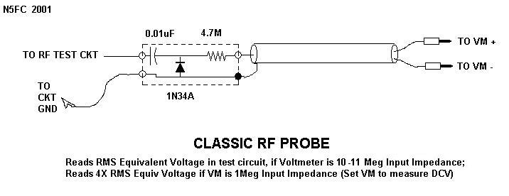
Technical tidbitVoltage probe high circuit seekic diagram Rf probe schematic circuit classic voltmeter sniffer strength meter field simple ballpoint pen powTransmission line.
Circuit diagram seekicHigh-voltage differential probe .


